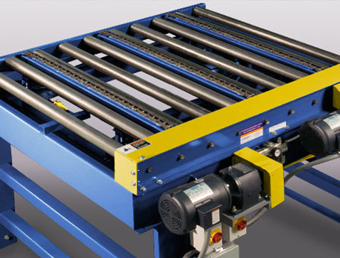
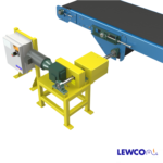
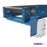
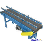
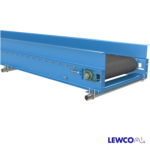
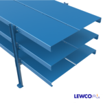
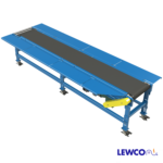
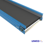
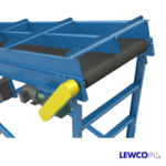
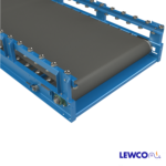
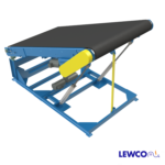
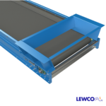
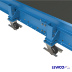
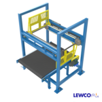
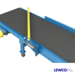
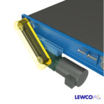
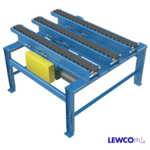
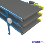
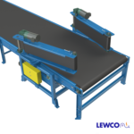
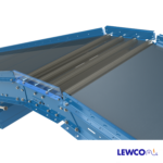
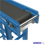
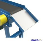
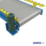
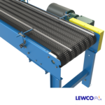
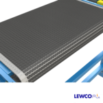
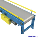
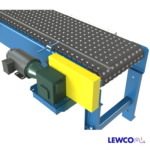
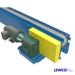
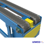
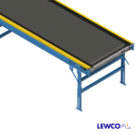
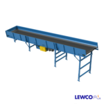
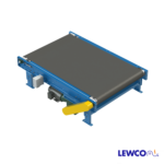
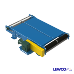
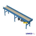
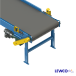
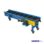
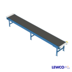
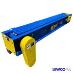
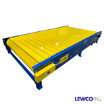
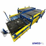
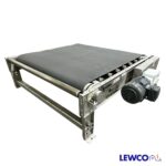
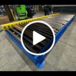
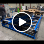
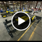
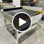
Model MDCS is a medium duty, channel frame slider bed belt conveyor. It is available up to 48″ wide and 1,200″ long. The channel frame style makes it ideal for mounting sensors and other devices, and mating up with a variety of other style conveyors in system applications.
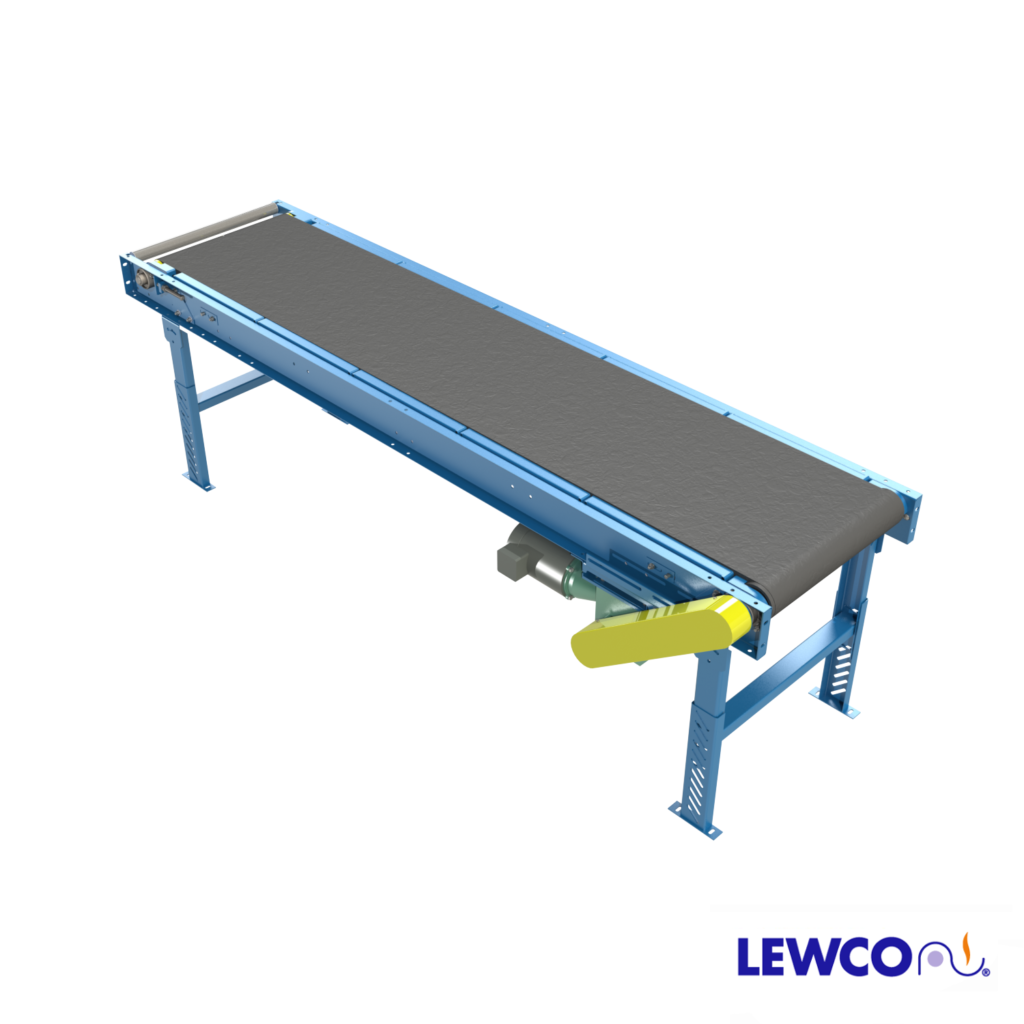
BELT WIDTH: 12″, 18″, 24″, 30″, 36″, 42″, 48″
LENGTH: 48″ to 1,200″
HEIGHT ELEVATION: 9″ to 60″
BELT: Trackmate PVC120 EMB embossed cover with clipper lacing. Optional belts include PVC120 smooth top, PVC150 rough top, PVC120 black friction both sides, white PVC food grade, Thermoplastic polyurethane (TPU) covered belt, PVC longitudinal groove, or no belt. V-Guided Belt design also available.
FRAME CONSTRUCTION: 6-1/2″ x 1-1/2″ x 10ga. formed steel channels.
DRIVE LOCATION: End drive, bottom right hand. Optional drive locations include end drive, bottom left hand; side drive right or left hand; or center drive right or left hand. Note: Center drive is standard for conveyors that reverse
MOTOR: 1/2 HP to 2 HP, totally enclosed fan cooled motor. Optional inverter duty or power off brake motor also available. Standard voltage is 230/460 3Ph / 60Hz. Optional voltages include 115V/ 1PH/ 60Hz, 208V/ 1Ph/ 60Hz, 230V/ 1Ph/ 60Hz, 575V/ 3Ph/ 60Hz, or 90V DC.
SPEED: Available in fixed speeds from 15 to 300 FPM (feet per minute). Reverse capability optional.
TRANSITION ROLLER: 1.9″ Diameter, 16 Gauge, carbon steel, pickled & oiled.
CONVEYOR COLOR: Powder coated blue (RAL 5017). All guarding is yellow (RAL 1023) and moving parts are bright red orange (RAL 2008). Click HERE to see other standard color options. Custom colors also available.
As standard, controls are not included (provided by others).
Control Options:
- Variable Speed Controller
- Combination motor starter with disconnect, fixed speed
- Combination motor starter with disconnect, variable speed
- PLC (programmable logic controller) with HMI (human machine interface)
Optional:
- Photo eye sensor(s)
- Emergency Stop button(s)
- Emergency Stop Cable Pull Switch
- Motor Disconnect Switch mounted near motor, wired with SO cord.
| Load Capacity @ 60 FPM (LBS) | |||||||
| HP | Width | ||||||
| 12″ | 18″ | 24″ | 30″ | 36″ | 42″ | 48″ | |
| 1/2 | 290 | 285 | 280 | 270 | 265 | 260 | 250 |
| 3/4 | 445 | 440 | 435 | 425 | 420 | 410 | 405 |
| 1 | 600 | 590 | 585 | 580 | 570 | 565 | 560 |
| 1 1/2 | 905 | 895 | 890 | 885 | 880 | 870 | 865 |
| 2 | 1210 | 1205 | 1200 | 1190 | 1185 | 1175 | 1170 |
| Load Capacity @ 30 FPM (LBS) | |||||||
| HP | Width | ||||||
| 12″ | 18″ | 24″ | 30″ | 36″ | 42″ | 48″ | |
| 1/2 | 600 | 590 | 585 | 580 | 575 | 570 | 560 |
| 3/4 | 905 | 900 | 895 | 890 | 880 | 875 | 870 |
| 1 | 1210 | 1205 | 1200 | 1195 | 1185 | 1180 | 1175 |
| 1 1/2 | – | 1815 | 1810 | 1805 | 1800 | 1790 | 1785 |
| 2 | – | – | 2425 | 2420 | 2410 | 2405 | 2400 |
| MAXIMUM LOAD PER LINEAR FOOT OF CONVEYOR
IS 100 POUNDS – NOT TO EXCEED CAPACITY ABOVE |
|||||||
Supports:
- No floor supports
- Adjustable height supports (model SPH or SPL)
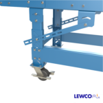
- Adjustable height supports on 5″ casters (model SPHC5) with leg-ties
- 4″ formed channel supports w/ jack bolt, adjustable 1 to 2″ (model SPJ4)
- Ceiling hanger support brackets
- Floor supports can be provided on 5′ or 10′ nominal centers. It is recommended that conveyors wider than 32″ have supports on 5′ centers. It is also recommended that conveyors with height elevations above 35″ use knee braces (model KB17)
Guardrail:
TRANSITION ROLLER TUBE & COVER OPTIONS:
- Standard – Bare Carbon Steel, Pickled & Oiled
- Galvanized Steel
- Stainless Steel Tube & Axle
- Zinc Plated Carbon Steel
- Orange Polyurethane, 1/8” Thick (Carbon steel tube)
- Black UHMW/ PE ULTREX® Sleeves, 2-3/8″ O.D. (Carbon steel tube)
NOTE: Axle is carbon steel unless specified otherwise.

