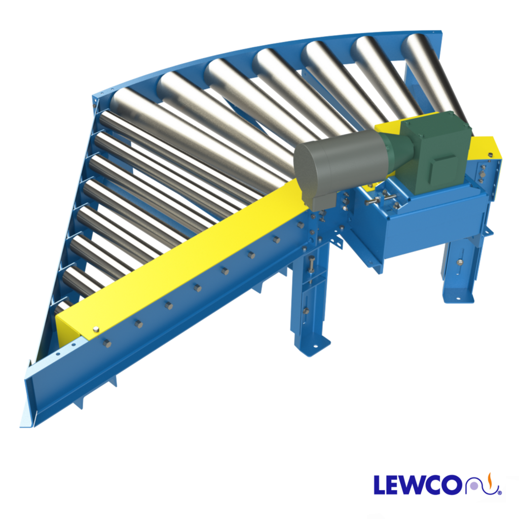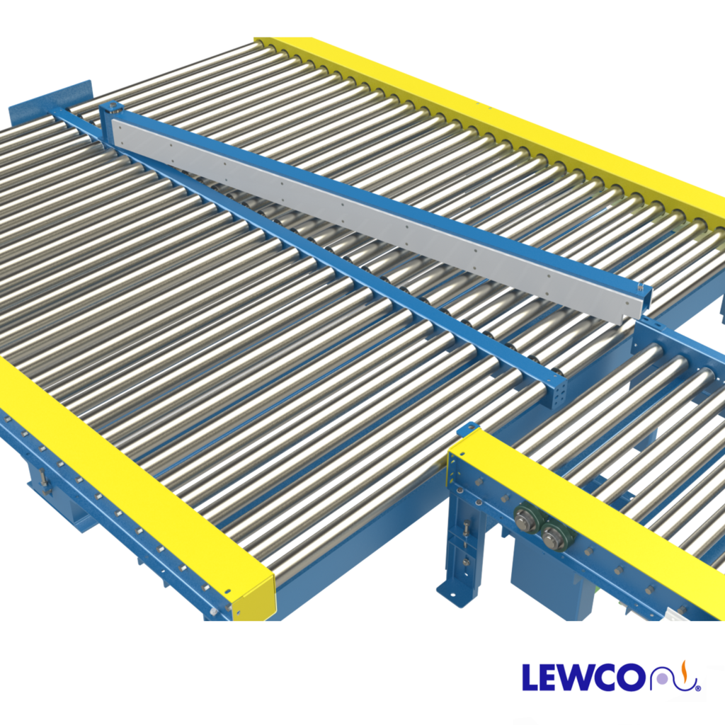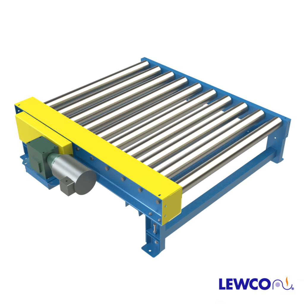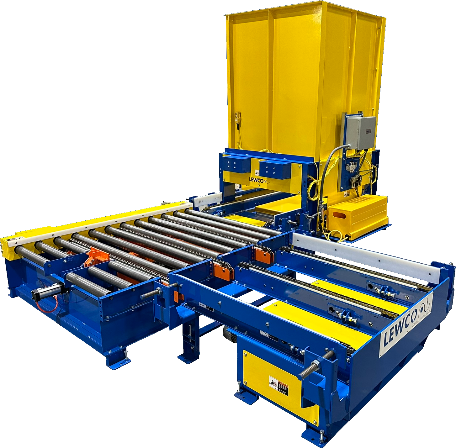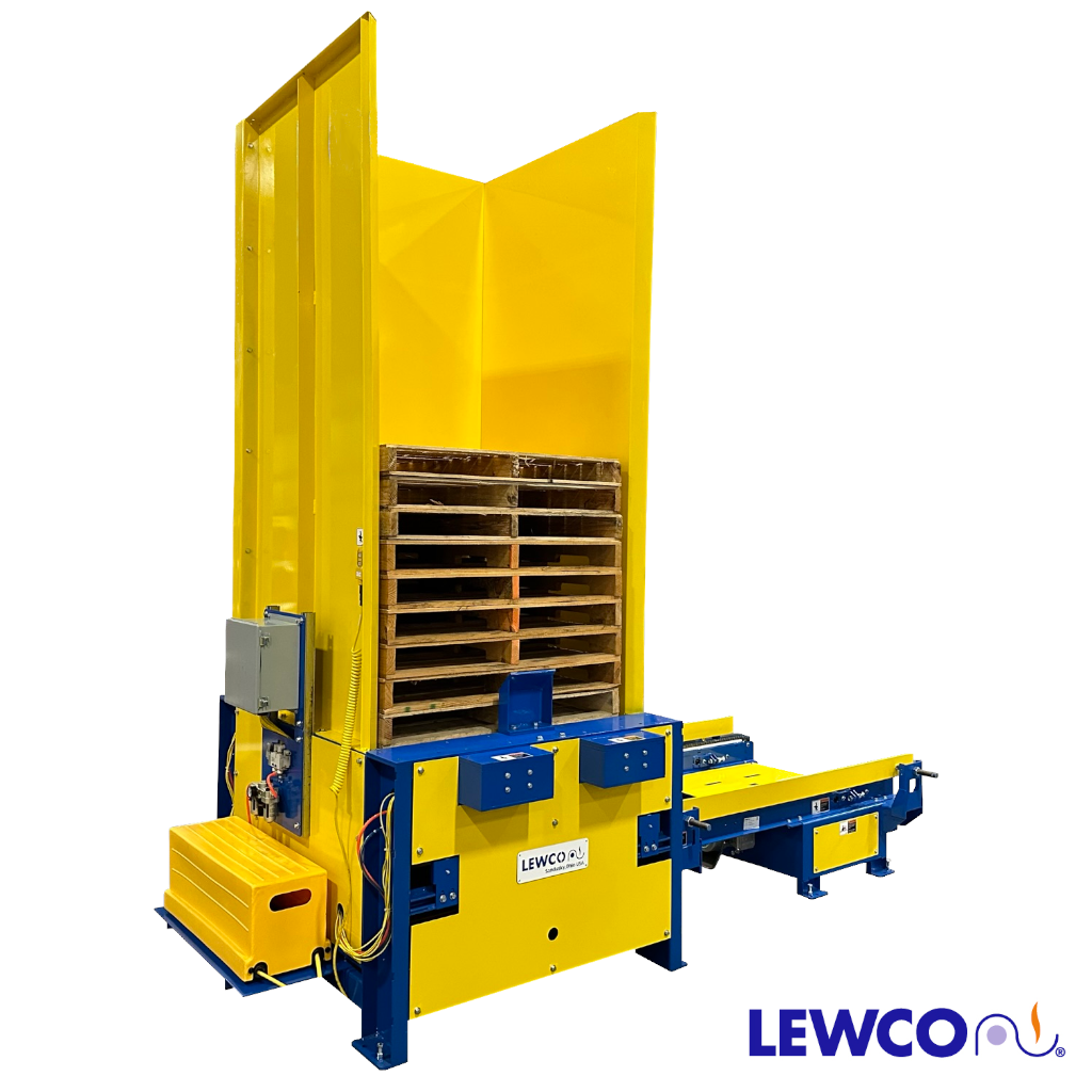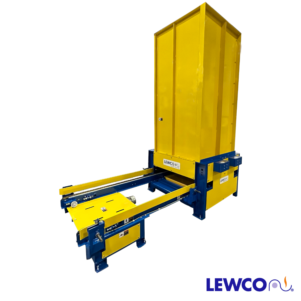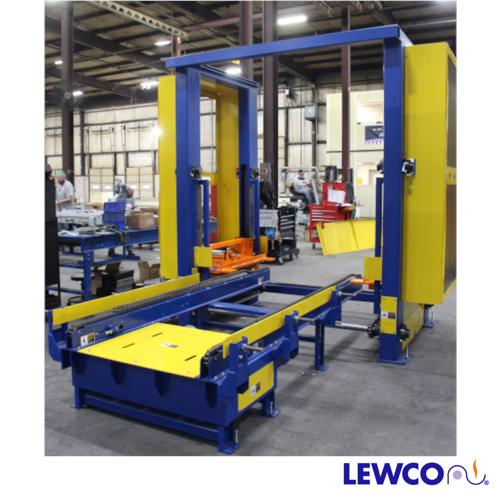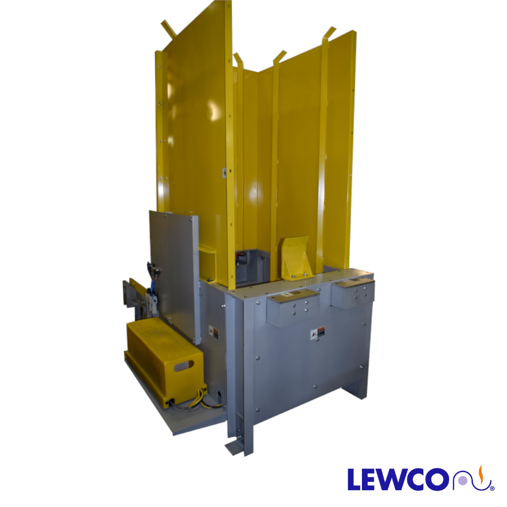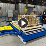
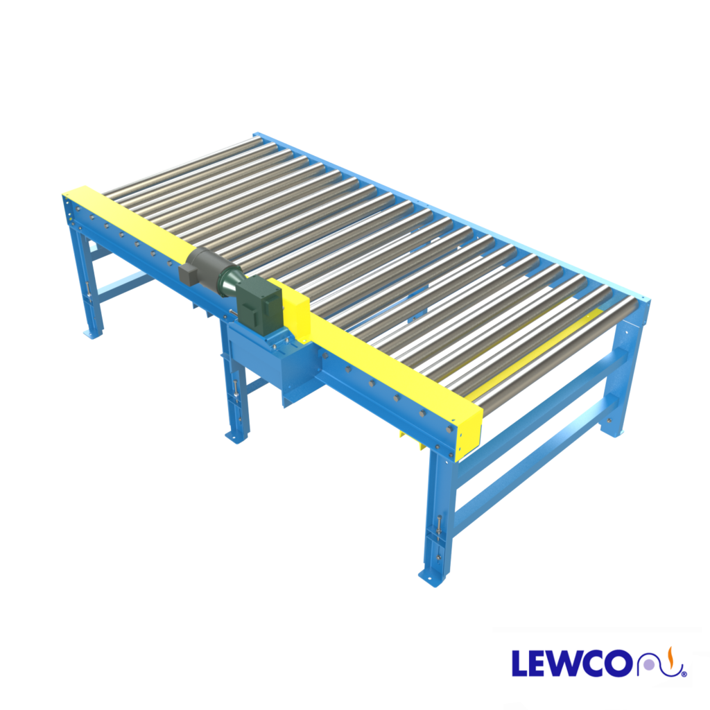
Chain driven roller conveyor is the workhorse of heavy-duty material handling and is an excellent choice for moving large automotive racks, structural steel beams, castings, and other heavy loads. Its rugged welded frame construction can withstand the most abusive of environments. Chain driven roller conveyor also provides versatility in production lines because it can easily incorporate with chain transfers and turntables.
EFFECTIVE WIDTH: 13″ to 84″
LENGTH: 48″ to 900″
BEGINNING HEIGHT ELEVATION: 9″ to 120″
ENDING HEIGHT ELEVATION: 9″ to 120″
ROLLER CENTERS: 6″, 7.5″, or 12″
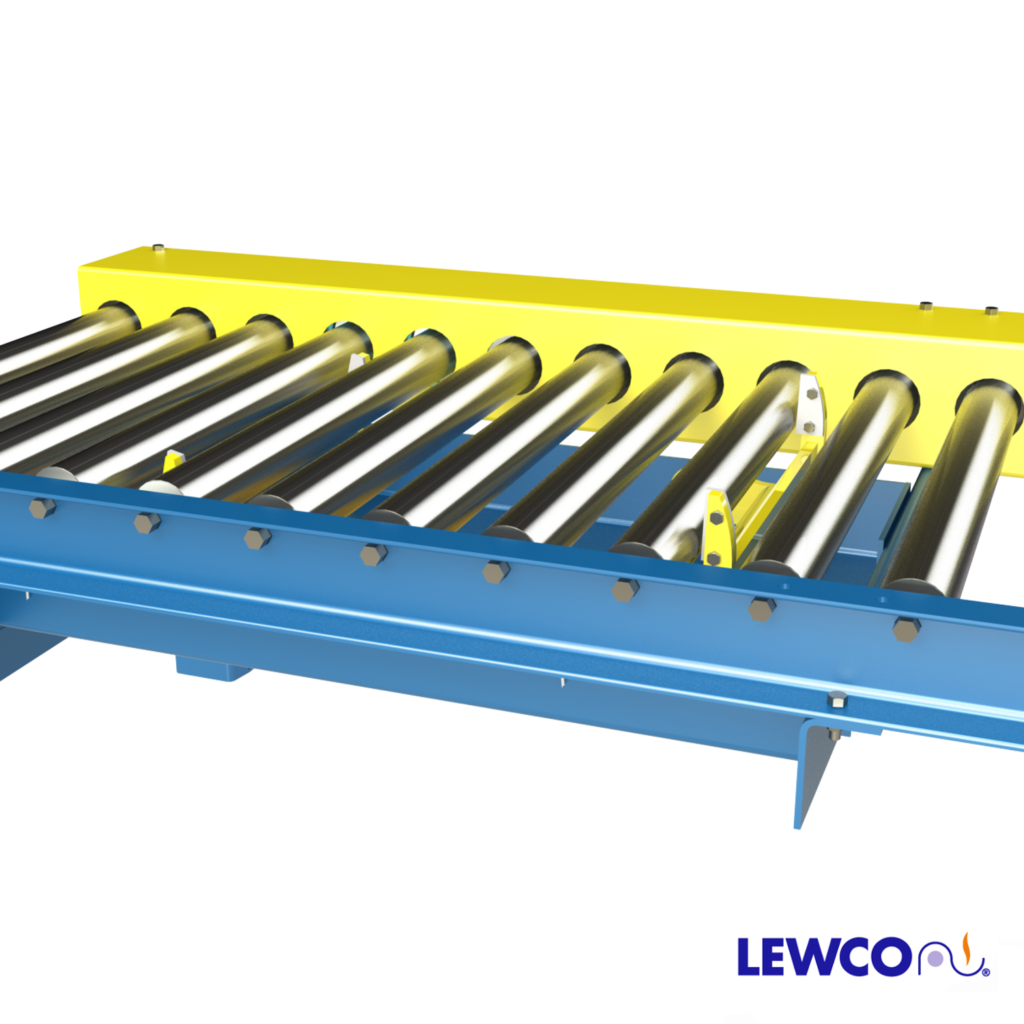
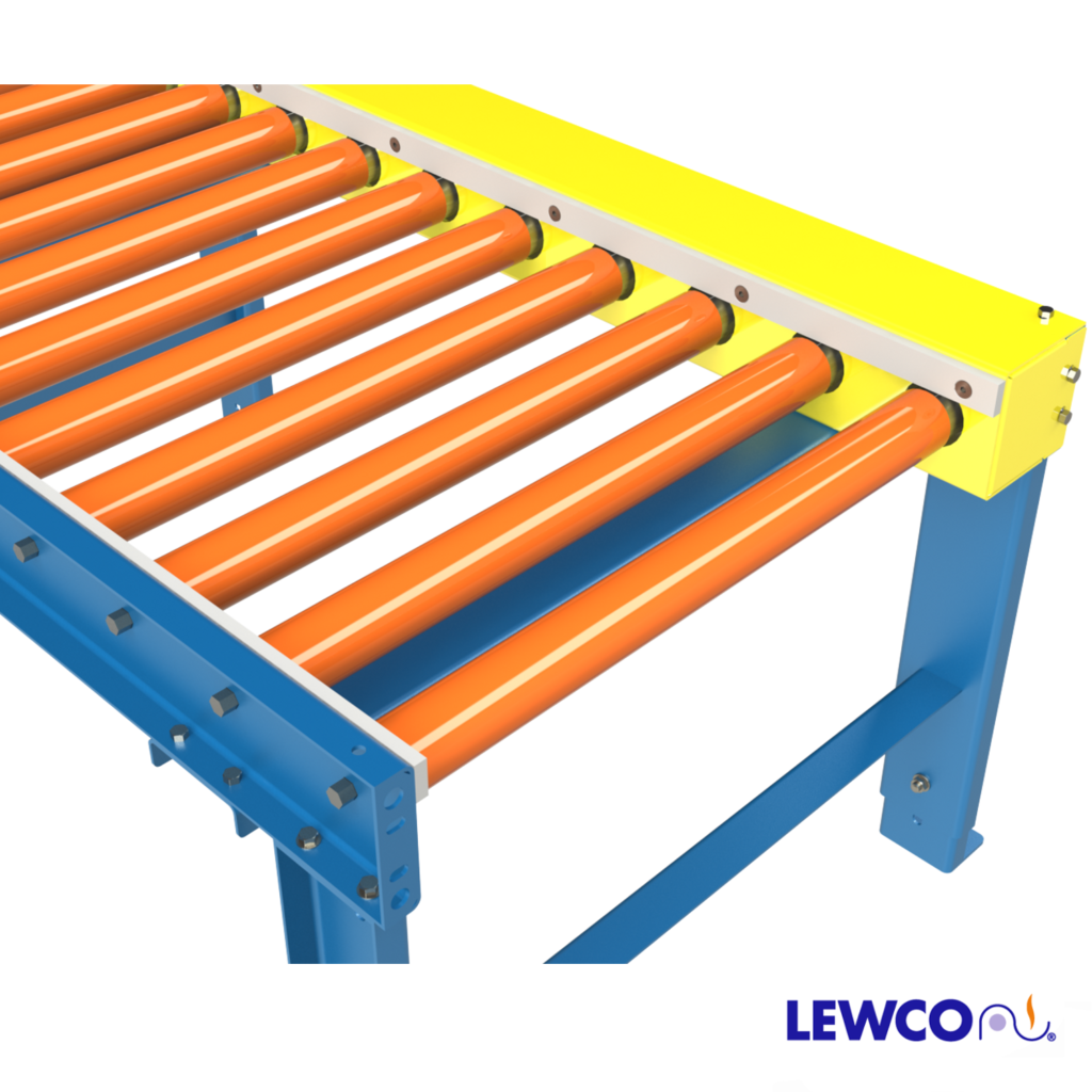
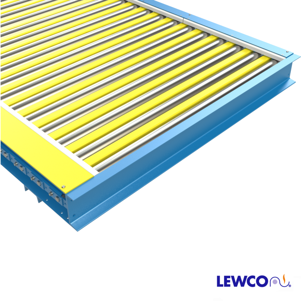
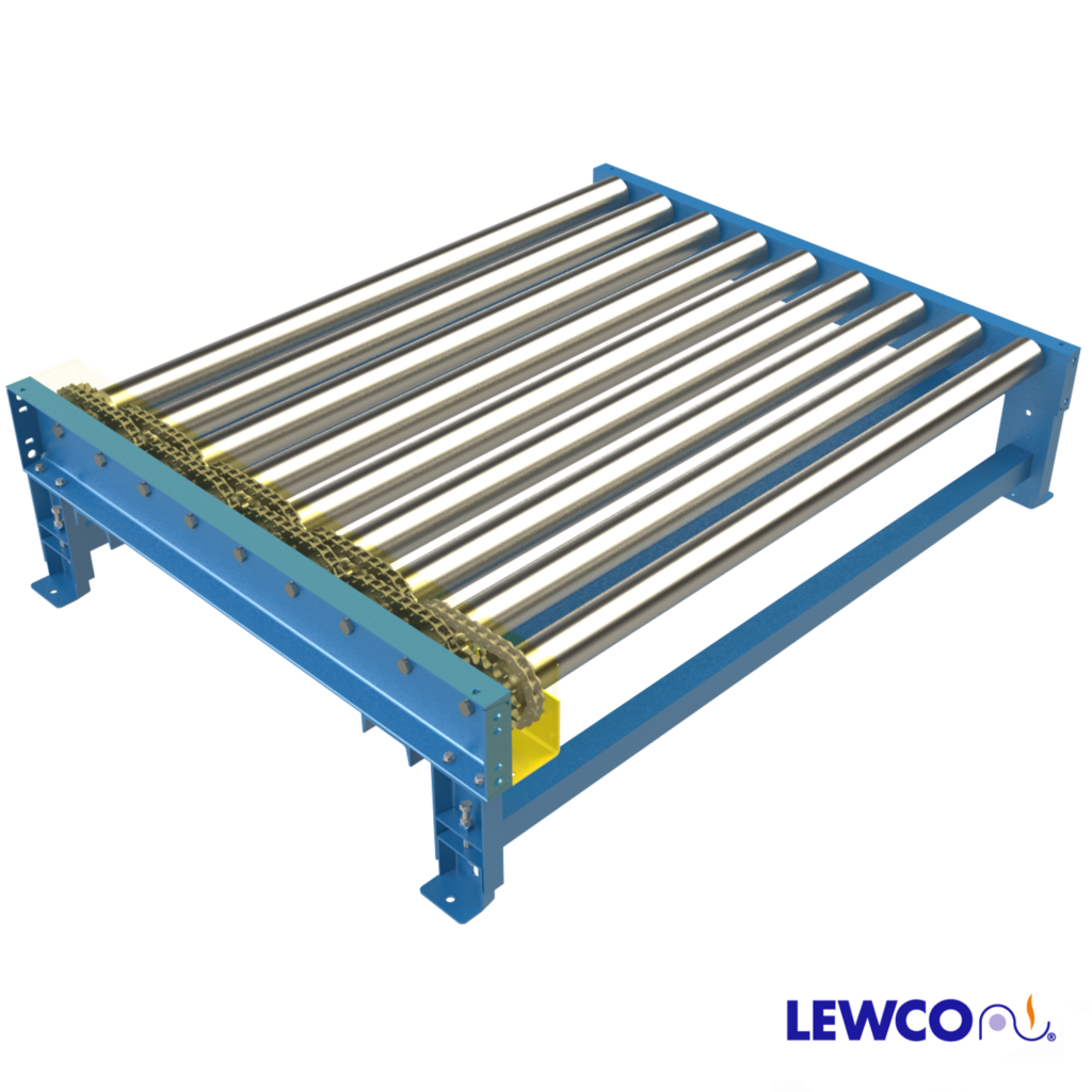
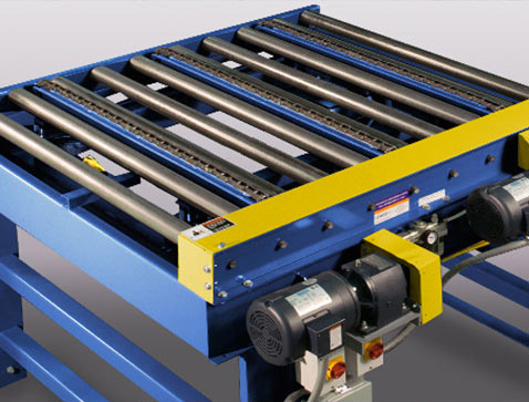
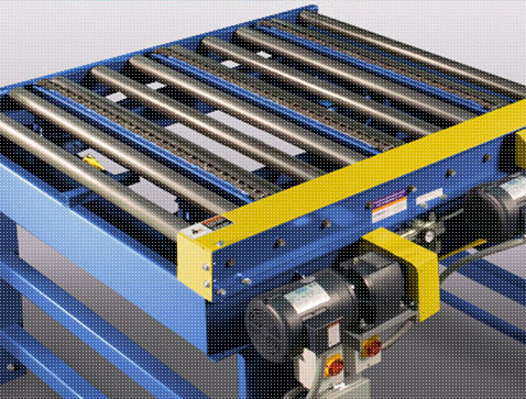
ROLLERS: 3.5″ dia. x .30 wall mild steel tube with 1″ hex axle, cotter pin retained, with precision, greased packed ABEC bearings, and #60 sprockets. Standard roller surface is carbon steel. Roller options include: zinc plated roller tube, polyurethane roller sleeves, and Ultrex accumulation sleeves.
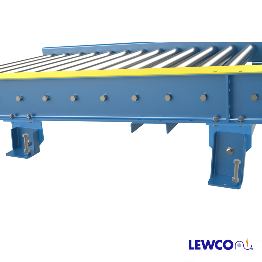
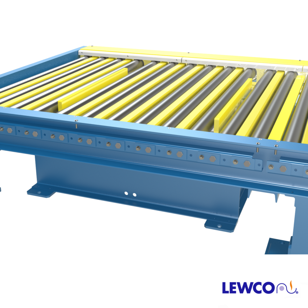
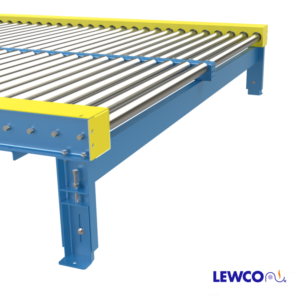
FRAME CONSTRUCTION: Standard frame includes structural channel 8″x11.5# on chain box side & 6″x8.2# on opposite side with rollers set 3/8″ high. Other frame options include:
- Structural channel 8″x11.5# with rollers set 1-5/8″ low.
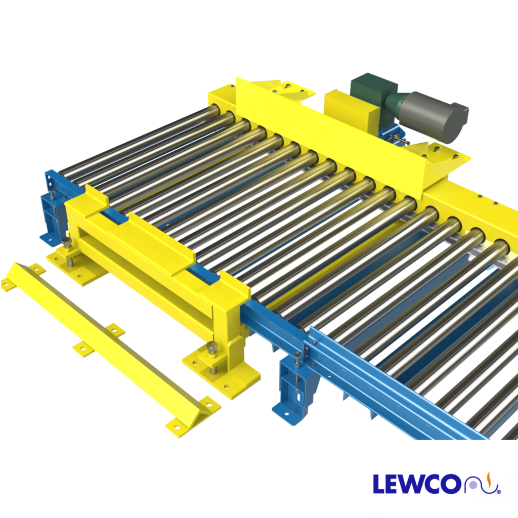
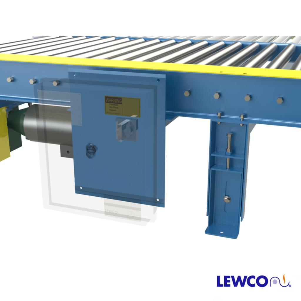
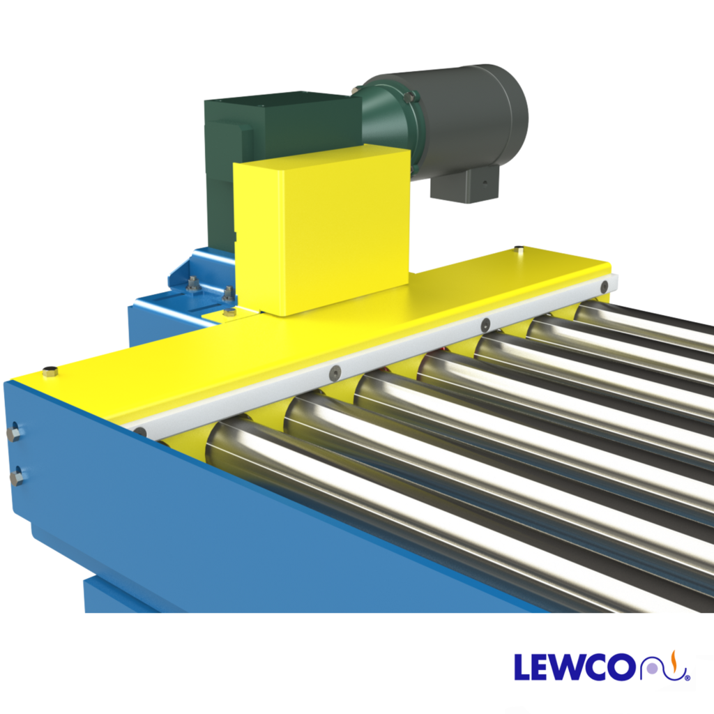
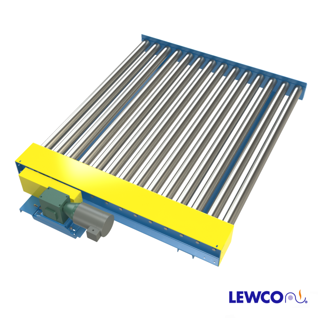
DRIVE LOCATION: Standard drive is mounted high near center of conveyor length on chain box side. Optional drives include drive mounted low or drive mounted below and within frame, near center.
MOTOR: 1/2 HP to 3 HP, totally enclosed fan cooled motor. Optional inverter duty or power off brake motor also available. Standard voltage is 230/460V/ 3Ph/ 60Hz. Optional voltages include: 115V/1Ph /60Hz, 208V/1Ph/ 60Hz, 230V/ 1Ph/ 60Hz and 575V/ 3Ph/ 60Hz.& 24VDC.
SPEED: Available in fixed speeds from 10 – 120 FPM (feet per minute)
CONVEYOR COLOR: Powder coated blue (RAL 5017). All guarding is yellow (RAL 1023) and moving parts are bright red orange (RAL 2008). Click HERE to see other standard color options. Custom colors also available.
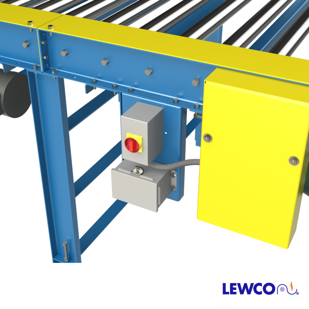
Conveyor Control Options:
- Variable Speed Controller
- Combination motor starter with disconnect, fixed speed
- Combination motor starter with disconnect, variable speed
- PLC (programmable logic controller) with HMI (human machine interface)
- No Controls (provided by others)
Optional
- Photo eye sensor(s)
- Emergency Stop button(s)
| Load Capacity (LBS) @ 60 FPM 4.5″ or 6″ Roller Centers | |||
| HP | Width | ||
| 36″ | 60″ | 84″ | |
| 1/2 | 300 | – | – |
| 3/4 | 1250 | 400 | – |
| 1 | 2200 | 1350 | 550 |
| 1 1/2 | 5050 | 4200 | 3400 |
| 2 | 9050 | 8200 | 7400 |
| 3 | 14350 | 13550 | 12750 |
| Load Capacity (LBS) @ 30 FPM 4.5″ or 6″ Roller Centers | |||
| HP | Width | ||
| 36″ | 60″ | 84″ | |
| 1/2 | 2850 | 2000 | 1200 |
| 3/4 | 5050 | 4250 | 3400 |
| 1 | 9050 | 8250 | 7450 |
| 1 1/2 | 14400 | 13550 | 12750 |
| 2 | 19700 | 18900 | 18100 |
| 3 | 30400 | 29550 | 28750 |
| Maximum load per linear foot of conveyor is 2000 LBS – not to exceed capacity above | |||
Options:
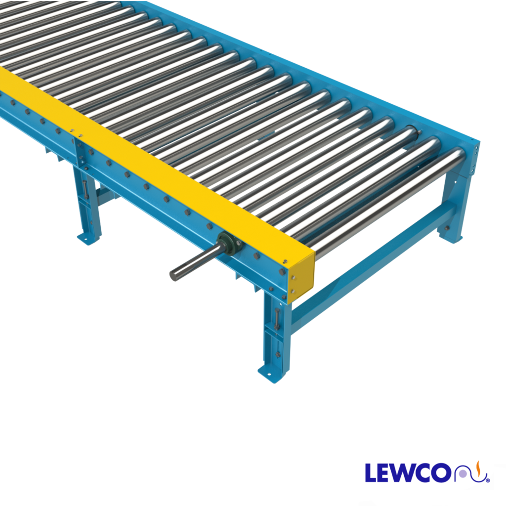
- Guardrail
- Fork truck barriers
Supports:
- No floor supports
- 5″ structural channel jack bolt supports, adjustable 1″ to 2″ (model SPSJ5)
- 5″ formed channel jack bolt supports, adjustable 1″ to 2″ (model SPJ5)
- Supports can be provided with optional adjustable top plate for conveyors on an incline or decline
- Floor supports can be provided on 5′ or 10′ centers. It is recommended that conveyors wider than 32″ have supports on 5′ centers. It is also recommended that conveyors with height elevations above 35″ use knee braces (model KB18)